





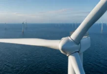
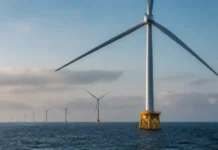

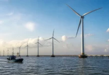






















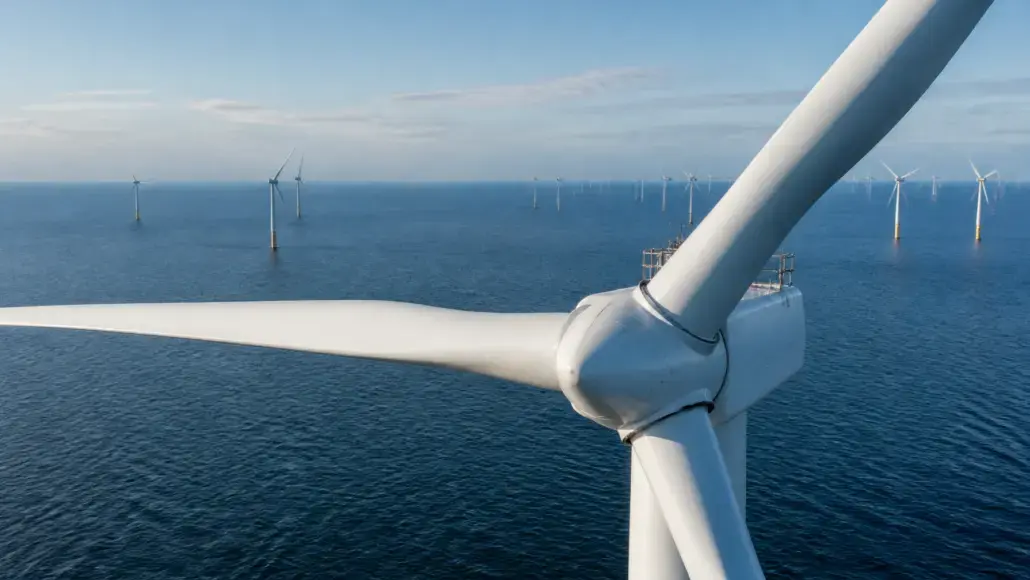

Wind turbine rotors have grown to diameters that now exceed 250 meters, and at that scale aerodynamic refinement delivers more value than any other single design lever. Every percentage point of improvement in lift-to-drag performance across a blade the length of a city block compounds into measurable annual energy production gains, which is why rotor aerodynamics has become one of the most actively funded research areas in the wind sector. Modern high-capacity turbines capture energy at capacity factors that were considered unattainable fifteen years ago, and much of that progress traces directly to how air moves over curved surfaces spinning at up to 90 meters per second at the blade tip.
The stakes are commercial as much as technical. A 15 MW machine with a 236-meter rotor, such as the Siemens Gamesa SG 14-236 DD, earns its keep across thousands of operating hours in partial load conditions, where the difference between a good airfoil and an excellent one is felt on every revolution. Developers comparing turbine platforms increasingly reward aerodynamic sophistication in their procurement scoring, because a rotor that extracts an additional one or two percent from the same wind resource raises project returns without adding a single tonne of steel or concrete.
Airfoil Design Evolution for Multi-Megawatt Rotors
The airfoils used on today’s largest blades bear little resemblance to the aviation-derived profiles of the 1990s. Wind-specific airfoil families are engineered for thick root sections that carry structural loads, transitional mid-span profiles that balance lift against thickness constraints, and slender tip sections optimized purely for efficiency. Designers now work with computational fluid dynamics models that resolve boundary layer behavior across the full operating envelope, capturing stall onset, laminar-turbulent transition and the effects of surface contamination in ways that wind tunnel testing alone never could.
One defining trend is the deliberate softening of aerodynamic behavior near stall. Early high-performance airfoils delivered outstanding peak lift but lost performance abruptly when flow separation began, creating fatigue penalties and control headaches. Contemporary profiles trade a modest amount of maximum lift for gentler post-stall gradients, which allows rotor designers to run higher tip speed ratios with less margin anxiety. Pre-bending and sweep of the blade planform add another layer of refinement: curving the blade away from the tower increases tip clearance without lengthening the tower, while geometric twist distributions ensure each spanwise section operates near its optimal angle of attack across changing wind speeds.
Thick airfoil research illustrates how specialized the field has become. Root sections on 150-meter blades approach 50 percent relative thickness, shapes that would be unrecognizable as wings but that carry bending loads millions of times over a design life. Designing acceptable transitions between such thick roots and efficient tips requires multi-objective optimization, balancing lift, drag, structural depth and manufacturing constraints at every spanwise station. The resulting geometries are now routine in serial production, but they encode years of accumulated fluid dynamics knowledge that separates competitive blade suppliers from the rest of the market.
Passive Flow Control on Large Blade Surfaces
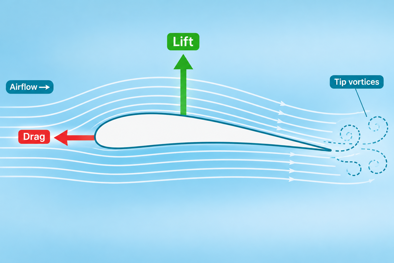
Large rotors suffer from aerodynamic problems that small machines barely experience. Tip vortices generate noise and drain energy, leading-edge erosion from rain, hail and insects roughens the surface over time, and flow separation near the root wastes a significant fraction of the swept area. Passive flow control devices address these losses without adding moving parts or maintenance burden, and their adoption across the industry has been swift.
The most established of these measures include:
- Vortex generators, small vanes mounted in rows along the suction surface, re-energize the boundary layer and delay separation, recovering several percentage points of performance that thick airfoils would otherwise sacrifice at moderate angles of attack.
- Serrated trailing edges, inspired by owl wing research, scatter the broadband noise generated at the trailing edge while preserving aerodynamic output, allowing higher tip speeds within regulatory noise limits.
- Gurney flaps and flexible trailing edge extensions reshape the effective camber of inner blade sections, boosting lift where the chord is widest and most structurally forgiving.
- Leading edge shields and protective coatings slow rain and particle erosion, preserving the clean surface profile that laminar flow designs depend on for years rather than months.
- Winglets and tip extensions redirect the energy that bleeds into tip vortices back into useful lift, a measure now appearing on serial-production offshore blades.
Field trials of these technologies have shown energy yield improvements in the range of one to five percent, with vortex generator retrofits on existing fleets providing some of the fastest paybacks in wind asset management. Because they are installed during manufacturing or during scheduled maintenance windows, they sidestep the certification complexity of major redesigns while still moving the production needle at farm scale.
Active Aerodynamic Control and Load Management
Passive devices set the ceiling on rotor performance, but active systems determine how consistently a turbine operates near that ceiling. Modern controllers continuously adjust blade angles, rotor speed and torque to hold each spanwise section at its optimal operating point, and the sophistication of that adjustment is growing rapidly. Coordinated rotor speed and blade angle schedules, refined using machine learning trained on SCADA histories, now adapt to the aerodynamic state of each individual machine rather than applying one generic curve to an entire fleet.
The interplay between aerodynamics and loads is where the newest value lies. Long blades flex under changing gusts, and that flexing changes the local angle of attack, which changes the loads again in a feedback loop that multiplies fatigue damage on rotors approaching 250 meters. Active flaps, trailing edge devices and tailored pitch schedules interrupt this loop by responding to measured or predicted load excursions in real time. The coordination of these responses with blade pitch control systems is one of the fastest-moving disciplines in turbine engineering, since it allows designers to lengthen blades further without paying a proportional fatigue penalty. Research published through 2025 demonstrates meaningful fatigue load reductions from such multivariable schemes, reductions that translate directly into lighter structures or longer design lives at constant weight.
Evidence from operating fleets supports the investment. Operators report that aerodynamic retrofit programs, combining flow control devices with recalibrated control schedules, have lifted annual energy production on older machines by amounts comparable to far costlier hardware upgrades. The pattern reinforces a broader lesson in rotor aerodynamics: value compounds when surface treatment, device selection and control software are engineered as one coherent system rather than procured separately.
Wake Effects and Farm-Level Aerodynamic Value
Rotor aerodynamics no longer stops at the nacelle boundary. The turbulent wake a large rotor leaves behind reduces the output of every turbine downstream, and farm layouts with tight spacing pay a persistent production tax in these losses. Aerodynamic improvements that narrow or weaken wakes therefore compound across an entire array rather than stopping at the source machine. Serrated and softer blade designs measurably reduce wake turbulence intensity, and rotor-aware layout optimization now treats each turbine’s wake signature as an input to the farm design rather than an afterthought.
Farm-level flow control extends the same logic into operations. Wake steering, in which selected turbines deliberately misalign a few degrees to deflect their wakes away from downstream neighbors, has moved from field experiments at the National Renewable Energy Laboratory into commercial pilot deployments, with modeling studies indicating annual farm output gains of one to two percent in favorable layouts. These gains depend on accurate aerodynamic models of rotor behavior, which is why the same airfoil datasets that drive blade design now also drive farm control software. The distinction between a blade designer’s problem and a plant operator’s problem is dissolving, and the organizations that manage aerodynamic knowledge across that boundary are extracting returns their competitors leave in the wind.
Validation, Standards and the Road Ahead
Proving aerodynamic performance at extreme scale is itself a discipline. Two-dimensional wind tunnel sections, scaled rotor tests and full-scale instrumentation campaigns each validate one layer of the design chain, and certification bodies now expect aeroelastic models that couple aerodynamic response with structural dynamics across the full operating envelope. Digital twins have sharpened this process further, letting engineers compare predicted and measured loads on operating machines within hours rather than months, and feeding deviations back into the next design iteration.
Independent verification also matters commercially. Developers financing projects worth hundreds of millions of dollars rely on certified power curves, and aerodynamic claims that survive third-party measurement command measurable premiums in turbine supply agreements. As competition in the 15 MW class intensifies, documented aerodynamic performance has become a differentiator that manufacturers defend with dedicated test campaigns, boundary layer instrumentation and, increasingly, full-scale rotor pressure measurements that were impractical a decade ago.
The next generation of gains is likely to come from morphing structures, adaptive camber surfaces and rotors whose geometry adjusts to site conditions over their lifetimes. For the power sector, the message from two decades of refinement is consistent: rotor aerodynamics is the highest-return engineering investment available in wind energy, converting fundamental fluid mechanics directly into kilowatt-hours sold. As turbines push past 20 MW, the rotors that dominate the next procurement cycle will be those whose surfaces, devices and control schedules were tuned together rather than designed in isolation.